Symbols and information commonly seen in piping diagrams

Piping equipment is essential in factories and construction sites. Even if you use it every day, when you look at a blueprint, you might find yourself wondering, "What is this symbol?"
The symbols on piping diagrams are simplified and many of them look similar, so it's no wonder you're confused.
This time, we will explain the meaning of the basic symbols in piping system diagrams and how to read drawing information including piping system diagrams.
1. What is a piping diagram?
A piping diagram is a drawing created to show the order of piping, components, and relative positions of equipment in devices and building facilities that require piping for liquids, gases, etc. It serves to convey information that cannot be expressed in a plan view, which only shows the view from directly above.
In addition to piping, system diagrams also include power system diagrams, low-voltage system diagrams, and duct system diagrams, and are one of the essential drawings for facility design and management.
2. Symbols commonly used in liquid piping
There are many different types of fluids that use piping diagrams, but here we will explain the symbols commonly used in liquid piping.
Piping diagrams basically use symbols to represent frequently appearing components and elements. Remembering the following symbols will reduce the time it takes to read and interpret piping diagrams, leading to improved work efficiency.
■ Symbol elements
The "symbol elements" commonly used in liquid piping diagrams are as follows:
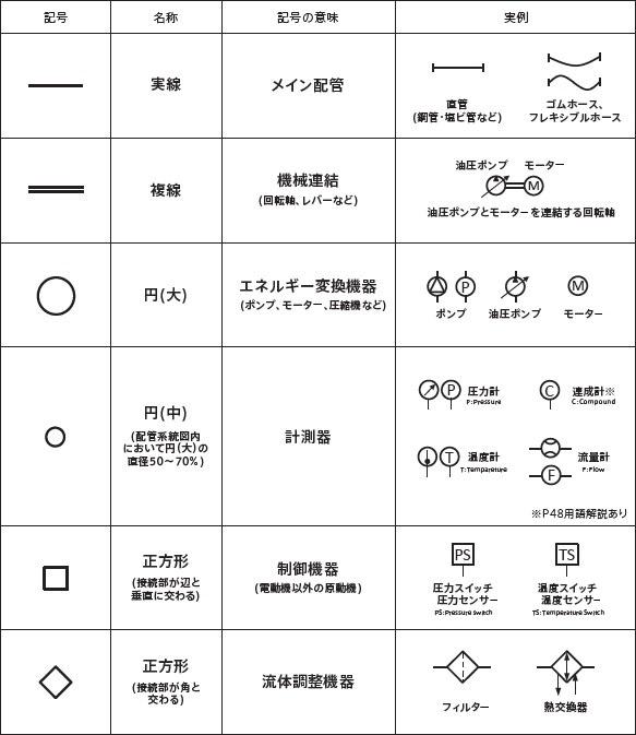
The main pipes are shown with solid lines, with straight lines indicating straight pipes such as PVC pipes or steel pipes, and curved or wavy lines indicating rubber hoses or flexible hoses.
Shapes such as circles and squares refer to equipment, and their meanings change depending on the shape, size, angle, and the characters inside. There are many similar notations, so it's important to remember the important symbols.
For example, piping is a solid line, but when it becomes a double line, it becomes a connected device such as a rotating shaft, and even though they are the same circle, a large circle indicates an energy converter and a small circle indicates a measuring instrument. Be careful not to confuse similar symbols.
■ Functional elements
Next are the "functional elements" that are commonly used in liquid piping.
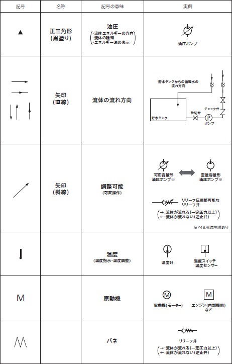
The arrows used in functional elements are straight horizontal or vertical arrows that represent the "direction of fluid flow," while diagonal arrows are symbols that indicate "variable operation is possible."
For example, if a hydraulic pump symbol has a diagonal arrow above it, it indicates that it is a variable displacement hydraulic pump.
In addition, the letter "M" is used as a symbol for a motor in the functional elements, but because it is similar in shape to the "spring" symbol, it must be interpreted in conjunction with the surrounding symbols.
These "functional elements" that represent the actual movement of fluids are very important symbols, so be sure to remember them.
■ How to connect the piping
The "piping connection methods" commonly used for liquid piping are depicted using the following symbols.
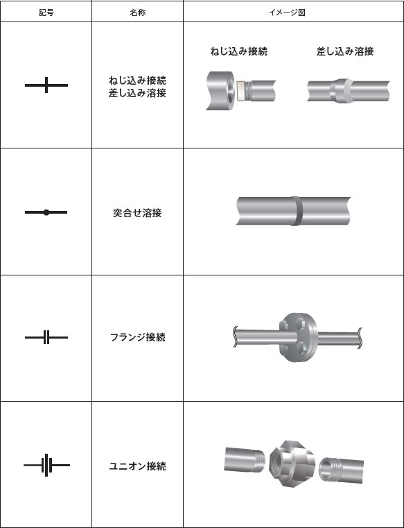
Be careful with small drawings, as the symbols for screw connections and butt welds can easily be mistaken for the arrows of functional elements. Also, remember that screw welds and socket welds have the same symbol.
If you can decipher these connection methods, you will be able to tell at a glance from the piping system diagram whether the relevant pipes are removable, such as flanged or threaded, or non-removable, such as butt welded.
■ Valves
Next, we will look at valves. Here we will summarize the valves that are commonly used in liquid piping.
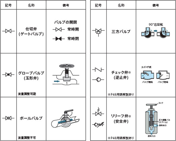
Most valves are display by two opposing triangles, but check valves and relief valves use distinctive shapes such as an N or a pointed wavy line.
Valves are shown in the shape of an "8." There are various types, such as gate, globe, and ball valves, but by placing them on the drawing, the control points in the process become clear.
■ Fittings (screw connection)
Finally, here is the notation for "fittings (threaded connections)" which are often used in liquid piping.
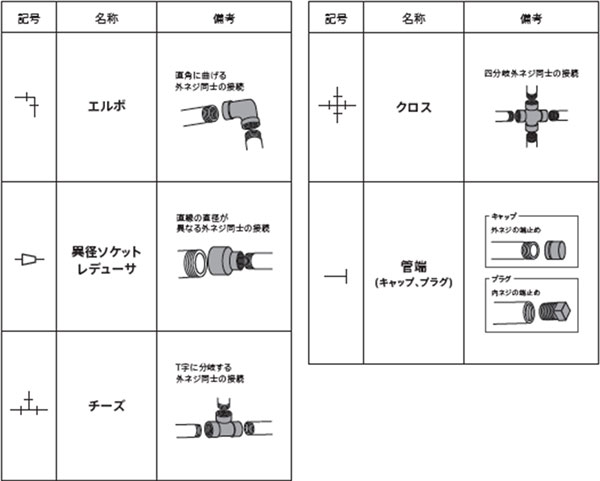
The symbol for a fitting is basically a straight line with a short line drawn on it, just like a threaded connection, but the same short line symbol is also used for caps and plugs that are attached to the end of pipes.
Fittings would be too detailed if they were listed on process piping, so they are often omitted from drawings and are mainly shown on parts list diagrams.
3. How to read the information on the piping diagram
From here, we will introduce piping system diagrams and how to read the information.
A typical piping system drawing consists of two main elements: a "piping system diagram" that shows the components of the piping equipment, and a "component parts list." The information can be interpreted by linking the piping system diagram and the component parts list.
Piping system diagrams use simplified symbols to indicate components, so component lists and balloons are used to indicate detailed information about the equipment used.
Ballooning is a method of drawing leader lines (balloons) from parts of a system diagram that require details, and then filling in the blanks on the drawing. You can write information directly in the balloons, or you can write the corresponding numbers from a component parts list.
The component parts list includes the part name, manufacturer, model, etc. of the equipment used, and by comparing it with the balloon number, you can see the details at a glance.
The piping diagram also contains important information about equipment specification, such as the flow rate, pressure, temperature, and expected values for various sensors within the piping.
4.まとめ
A piping system diagram is a drawing that shows the components of piping and their relative positions in relation to equipment, and its role is to convey information that cannot be shown in a floor plan.
Because it is difficult to depict in detail the parts and equipment commonly used in piping on drawings, simplified symbols are used.
Drawings used for liquid piping equipment include piping system diagrams made up of symbols and a supplementary component list, and it is necessary to combine the information to correctly interpret them. Understand the main symbols and the structure of the drawings to work efficiently.