Important points regarding piping of the liquid tank and its surrounding areas

In factories, liquid tanks and the piping around them are very important. Depending on the pump's position relative to the liquid tank, backflow of fluid or pump blockage may occur, which could have a major impact on line operation. In addition, it is important to properly install bypass circuits so that in the unlikely event of such a problem occurring, equipment maintenance or replacement can be performed while the factory is operating. This time, we will explain in detail the key points of piping around liquid tanks in factories.
When working around liquid tanks such as water or oil tanks, it is necessary to select a valve that matches the liquid level and pump position, and then install and use it correctly. The pump position relative to the liquid level can be confirmed visually, but this time we will explain using a piping diagram.
1. Piping points when the pump is below the liquid level
First, we will explain the piping points when the pump is installed below the liquid level.
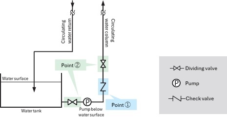
■ Point 1. Install a check valve
If the pump is located below the liquid level, gravity may cause the fluid in the piping to flow back into the tank when the pump is stopped, which may result in air pockets. Therefore, it is important to install a check valve on the pump discharge side to prevent air pockets.
A check valve, also known as a non-return valve, not only prevents backflow of fluids but also prevents return water hammer. There are five types of check valves: swing type, wafer type (wing type), disc type, ball type, and lift type. Each type has a different structure and purpose of use, so be sure to select the most suitable valve based on the piping situation, space, fluid, etc. of your factory.
■ Point 2. Open the gate valve
Gate valves are valves used to allow or stop the flow of fluids, and are installed at various points in piping to temporarily stop the flow of fluids in preparation for equipment maintenance or part replacement.
If the sluice valve is closed when the pump is running, the pump may be damaged due to blocked operation, so be sure to keep the sluice valve "open" when the pump is running.
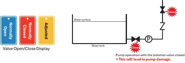
To ensure foolproof operation, it is also necessary to install a "valve opening/closing display" and take measures to prevent incorrect operation.
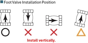
2. When the pump is above the liquid level, the foot valve is the key
If a pump is placed above a liquid tank, stopping the pump will cause the fluid to flow back into the tank through the piping. Therefore, it is important to install a foot valve, which functions in the same way as a check valve, to prevent backflow.
The foot valve is installed in the water tank as it is attached to the suction pipe side of the pump.
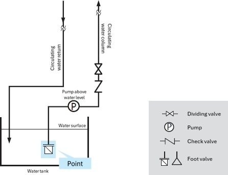
Please note that due to its structure, the foot valve may not function properly if it is not installed in the correct orientation, so be sure to install it perpendicular to the liquid tank.
3. Be careful of blocked operation around the liquid tank
Blocked operation can lead to damage to equipment, so if the circulation path around the liquid tank becomes blocked, it could affect line operation.
Therefore, risk hedging is required for equipment that is likely to become blocked or that will have a major impact if blocked, so we will explain the detailed methods below.
Equipment that is likely to become clogged: filter (clogged filter), heat exchangers (clogged due to foreign matter accumulation), valves (malfunction due to foreign matter getting caught)
Equipment that is most affected when blocked: Pumps (high unit price, long delivery time, operation of the entire line stops)
■ Managing differential pressure with a pressure gauge
The more clogged filter or strainer becomes, the greater the difference in pressure between the inlet and outlet sides will be, so install a pressure gauge at each of the inlet and outlet to check the pressure.
By managing the differential pressure, you can accurately determine when to replace filter and prevent blocked operation.
■ Install a relief circuit
It is effective to install a relief circuit with a relief valve in addition to heat exchangers and filter to prepare for blocked operation.
The fluid can be diverted, allowing for continuous circulation even in the event of a blockage.
■ Choose a pump with a blockage prevention function
Some pumps have a built-in relief circuit. For example, the oil pump in the piping diagram below opens the relief valve and relieves pressure when the pressure exceeds 1.0 MPa.
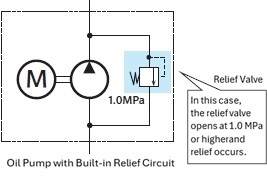
You may want to consider installing it in important piping sections.
4. Bypass circuit to prevent line stoppage
Normally, the main liquid circulation route used in production equipment is in constant operation during production, but if a malfunction occurs in the piping components, the operation of the entire equipment or the entire line must be stopped. Therefore, in areas where there are many malfunctions, installing a bypass circuit in advance can prevent the entire line from being shut down to some extent.
Finally, let's take a closer look at the three components that enable component replacement without stopping production.
<Components that are often assumed to have the potential for malfunctions>
Pump: As it is the power source for the fluid, if it breaks down it will not be able to operate.
filter, strainers...if they become clogged, the pathways may become blocked.
Valves (especially motor valves, solenoid valves, etc.) - Because they frequently fail.
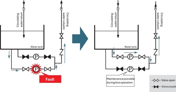
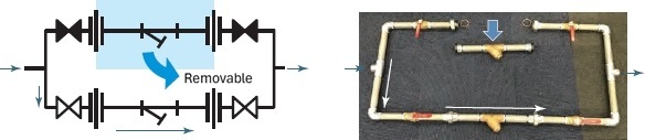
■ Pump
If a spare pump is installed next to the pump, it can be quickly restored by simply switching the gate valve, and maintenance can be performed while the equipment is still in operation.
■ filter and strainers
Just like with pumps, it is also effective to install gate valves on filter and strainers. By installing gate valves on both ends, maintenance and replacement work can be carried out while the system is running if a problem occurs.
In addition, if a union or flange is placed between the strainer and the gate valve, the equipment requiring maintenance can be removed from the piping.
■ Valves
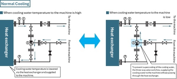
We recommend creating a bypass circuit using a gate valve for maintenance in case of malfunctions with valves such as motor valves and solenoid valves. As an example, let's look at a case where a three-way valve (solenoid valve) is used in a temperature control line for equipment cooling water.
The piping diagram below shows that cooling water is cooled by passing it through a heat exchanger, and when the temperature of the cooling water drops, a three-way valve switches to prevent it from overcooling, and the water is circulated directly to the equipment without passing through the heat exchanger.
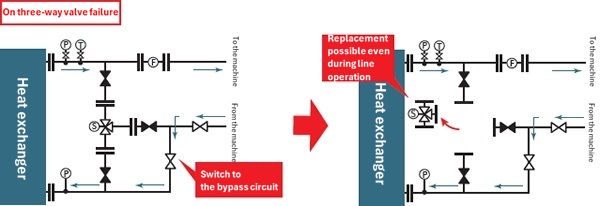
If this three-way valve fails, it is effective to close all of the gate valves installed before the three-way valve. By opening the gate valve of the bypass circuit that was created in advance and guiding the fluid, it becomes possible to replace the three-way valve without stopping the circulation of cooling water.
5.まとめ
It is important to utilize valves in the piping around the liquid tank to ensure trouble-free operation.
For example, if the pump is below the liquid level, installing a check valve or gate valve, or if it is above the liquid level, installing a foot valve will help reduce problems.
In addition, using a pressure gauge and installing a relief circuit are effective ways to prevent blocked operation. However, even if you take these measures, there is still a possibility that unexpected trouble may occur. It is a good idea to create a bypass circuit to hedge against the risk of a problem occurring and not affect line operation.