How to read piping diagrams and tips for improving cooling

In manufacturing processes, efficient supply of cooling water and stable cooling and temperature control are essential for preventing equipment problems and improving productivity.
It is difficult to visually inspect the inside of equipment piping through which cooling water passes, so if a problem does occur, it can take a long time to identify the cause.
However, piping diagrams contain many hidden hints that can lead to improvements when such problems occur.
This time, we will explain in an easy-to-understand manner how to read piping diagrams and how to improve cooling.
1. How to interpret a piping diagram
Equipment diagrams with many piping systems can look complicated, but they can be easily understood by following the steps. Specifically, the basic flow is as follows:
1. Understand the role of the equipment → 2. Classify the piping → 3. Identify the heat source
First, understand the roles of equipment such as tanks, water-cooled heat exchangers, and pumps, and then classify the piping that connects them. Color-coding the piping by fluid type will make it easier to understand the overall picture. Finally, identify the heat source that requires cooling.
2. How to read the piping diagram from the raw material tank to the mixing process and tips for improving cooling
Now, let's actually analyze it using a piping diagram from the raw material tank to the mixing process.
■ Step 1. Understand the overview of the equipment
First, get an overview of the entire piping system, including the roles and relationships of each piece of equipment, from the symbols on the piping system diagram.
In the diagram below, the orange areas indicate that room temperature raw materials are sent from storage tanks A and B to their respective raw material tanks, and the temperature is regulated by chiller 1.
In the blue area, two types of raw materials supplied from each raw material tank are transported to a mixing tank where they are stirred and mixed, and Chiller 2 adjusts the temperature to the appropriate level.
The green part shows that the motor valve adjusts the amount of raw material fed to the mixing tank, returning some of the unnecessary raw material to the raw material tank. The purple part is where the finished mixed raw material is fed to the next process.
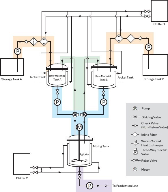
By color-coding each area in this way and understanding the relationships and roles of each piece of equipment, it becomes easier to understand the overview of the entire piping system diagram.
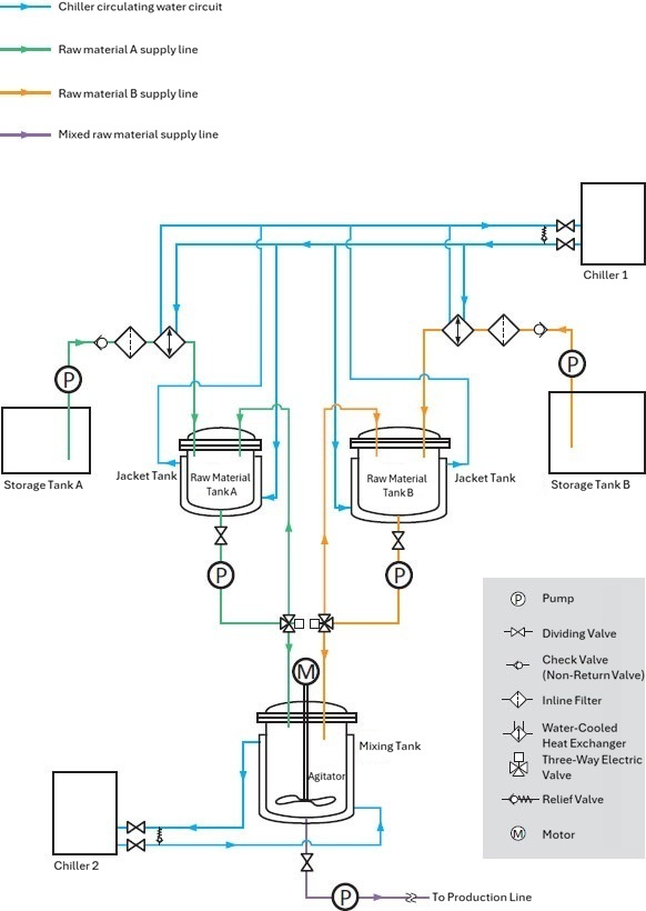
■ Step 2. Classify the piping by system
Next, let's color-code the pipes according to the fluid that flows through them.
Here, the chiller's cooling water circulation circuit is shown in light blue, the supply line for raw material A is shown in green, the supply line for raw material B is shown in orange, and the supply line for mixed raw materials is shown in purple.
This makes it possible to see at a glance which fluids are flowing through which pipes.
■ Step 3. Identify the heat source
Finally, identify the heat source. If you are going to improve the cooling to increase the efficiency of your machine, you need to accurately identify the heat source.
Heat sources include the heat generated in the process of adjusting the temperature of raw materials in the raw material tank, the room temperature raw materials in the storage tank, heat generated by the pump, and heat entering from the outside air.The process of creating mixed raw materials in the mixing tank also generates heat from the agitator and reaction heat.
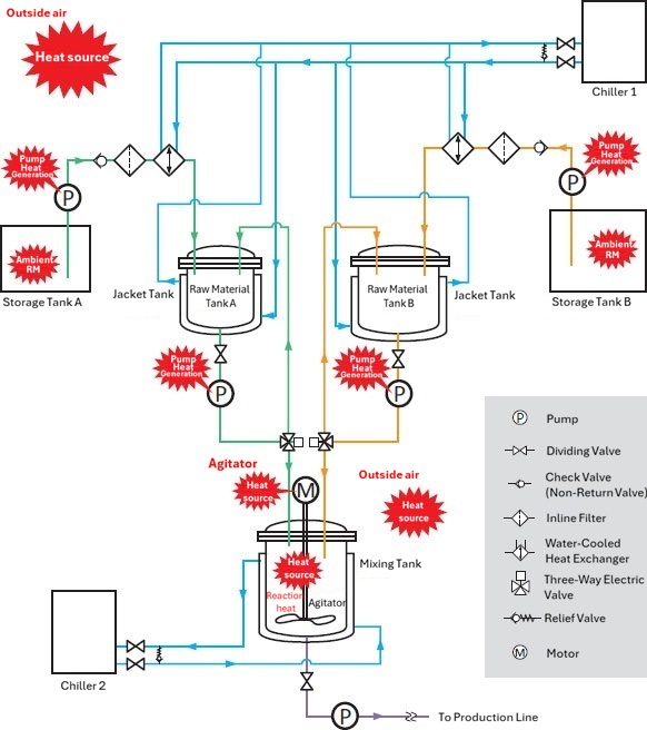
Identifying heat sources is very important in the production process. Information such as cooling the heat generated by machinery, adjusting the temperature when mixing raw materials, and the temperature difference between room temperature and raw materials, which is greatly affected by the outside temperature, is essential for calculating cooling capacity.
Identifying these heat source locations allows for efficient and precise cooling.
3. How to read hydraulic system piping diagrams and tips for improving cooling
Here are some tips for reading and interpreting hydraulic system piping diagrams. Hydraulic systems come in a wide variety of types, from simple to complex, so if you're not used to reading system diagrams, it can be difficult.
Let's read through the hydraulic system piping diagram in two steps.
■ Step 1. Classify hydraulic components
A hydraulic system can basically be divided into five parts: hydraulic cylinders (hydraulic actuators), valves, hydraulic pumps, hydraulic tanks, and accessories.
| Hydraulic Actuator | Converts pressure energy into work. Examples: Hydraulic cylinders, hydraulic motors, oscillating actuators |
|---|---|
| Valve | Controls the transmission of energy in the hydraulic fluid. Ex.) Pressure control valve, flow control valve, directional control valve |
| hydraulic pump | Supplies pressurized hydraulic oil. |
| hydraulic tank | Stores hydraulic oil. |
| accessories | Helps ensure the hydraulic system functions properly. Examples: heat exchangers, filter, instruments |
In the piping diagram of a hydraulic system circuit like the one below, you can see that the piping extending from the hydraulic actuator passes through valves such as flow control valves and solenoid valves, passes through the hydraulic pump, passes through an air-cooled radiator and filter, and flows into the hydraulic tank.
The hydraulic system can be understood as a whole by understanding the roles of its components, so there is no need to color-code the fluids as with raw material tanks.
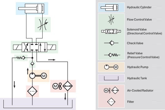
■ Step 2. Identify the heat source
The main heat source in hydraulic systems is the hydraulic pump.
Hydraulic pumps are a power source that applies pressure and flow to hydraulic oil, but at the same time, they also become a heat source as the temperature of the hydraulic oil rises, and the generation of heat above a certain level is unavoidable due to their structure.
Especially for large hydraulic units, it is necessary to prepare a machine to cool the hydraulic oil. It is recommended to use a heat exchanger or similar to set the target temperature to around 35 to 55°C.
4.まとめ
Piping diagrams that use specialized symbols can appear very complicated at first glance, but if the diagram is used to move fluids such as raw materials, it is easy to understand the overview of the equipment for each section and identify the heat source by color-coding the pipes for each fluid.
Even in the case of piping diagrams for a wide variety of hydraulic equipment, the overall picture can be seen by classifying the components of the hydraulic system.The hydraulic pump, which is the main heat source, should be properly equipped with a heat exchanger or similar device to control temperature.
Accurate interpretation of piping diagrams helps to effectively cool the necessary areas, improving productivity and extending the operating life of machinery.