How to determine pump capacity
Meeting the required head (the height to which the pump can push the liquid) is an essential requirement when selecting a chiller.
The pump power required to circulate cooling water can be expressed as "head."
The head varies depending on the condition of the piping connecting the chiller to the load (equipment).
Below we will introduce how to calculate the head based on piping conditions, etc.
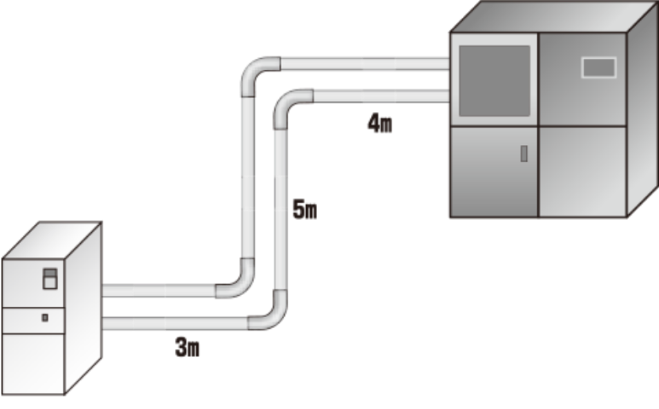
STEP 1Calculate the pipe length
Length of piping from chiller to device: 3 + 5 + 4 = 12 m × 2 (round trip) = 24 m❶
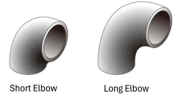
STEP 2Convert the fitting resistance into straight pipe length and add it to the piping length
The equivalent length of straight pipe for the fitting can be found from the table. From the table, a threaded 90 ° short elbow of 25A is 1.6m.
1.6×4 (places) = 6.4m❷ ❶+❷=24m+6.4m=30.4m❸
| name | Joint Shape | Pipe diameter (upper B) (lower mm) | ||||
|---|---|---|---|---|---|---|
| 1 | 1¼ | 1½ | 2 | 2½ | ||
| 25 | 32 | 40 | 50 | 65 | ||
| 90 ° Short Elbow | Screw | 1.6 | 2.0 | 2.3 | 2.6 | 2.9 |
| flange | 0.5 | 0.6 | 0.7 | 0.9 | 1.1 | |
| 90 ° Long Elbow | Screw | 0.8 | 1.0 | 1.0 | 1.1 | 1.1 |
| flange | 0.5 | 0.6 | 0.7 | 0.8 | 0.9 | |
Since resistance varies depending on the shape of the joint, check the value converted into straight pipe length in the table above.
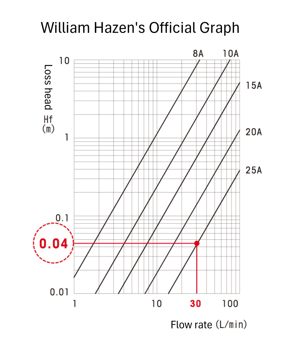
STEP 3 Calculate the "head loss* Hf (m)" from the flow rate and pipe diameter and multiply it by the total pipe length from "STEP 02".
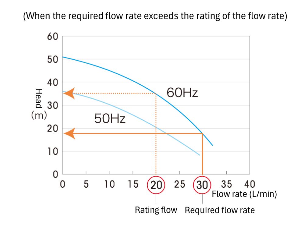
For a flow rate of 30 L/min and a pipe diameter of 25 A, see the graph on the right.
Hf=0.04Hf(m)❹ ❸×❹=30.4×0.04=1.2(m)❺
*Head loss: Pressure due to pipe friction expressed per 1m of pipe length for each pipe diameter and flow rate.
*William Hazen formula Hf=5.4775×10⁻³・C-1.85・D-4.87・Q1.85・L・α
(C: flow velocity coefficient, D: inner diameter of pipe, Q: flow rate, L: pipe length, α: safety factor)
STEP 4Add the rising height from the chiller to the equipment to calculate the head.
Flow rate 30L/height from chiller to device: 5m... ❻
❺+❻=1.2(m)+5(m)=6.2(m) The required lift is 6.2m❼
STEP 5 Select a pump that satisfies the head calculated in STEP 04.
Flow rate 30L/The head capacity of the chiller shown in the graph is 19m (at 60Hz) when the flow rate is 30L/min.
Therefore, the head capacity of this chiller meets the required head (6.2 m).
19m > 6.2m