
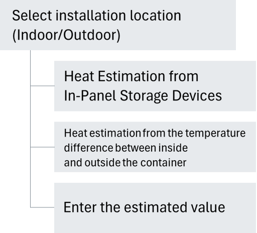
Basics of heat calculation
Estimated total heat generation=(rating output of each device inside the panel x heat loss ratio x number of devices)
Sum of
Key points for calculating heat quantity
① List the rating output and number of devices inside the panel.
②If there is a parts list, check rating output and number of devices listed on the list.
(3) If you actually look at the panel and list it, open the door and check the type, rating output, and number of equipment on board.
④ Look up the heat loss ratio of the relevant device from the "List of heat generation by device in panel."
Reference link → List of heat output by equipment
| Equipment stored inside the panel | Heat output (general guideline) | |
|---|---|---|
| AC servo amplifier | rating Output ~0.1kVA about 40% ~0.5kVA approx. 10% ~1kVA about 8% ~3kVA about 5% |
~5kVA approx. 4% ~11kVA about 3.5% ~22kVA about 3% |
| inverter | rating Output ~0.4kW approx. 12.5% ~0.75kW approx. 11% ~1.5kW approx. 8% ~2.2kW approx. 7% ~3.7kW approximately 6% |
~7.5kW approx. 6% ~11kW about 5% ~22kW approx. 4.5% ~30kW around 4% |
*For a 3.7kW inverter, the power output is 3.7kW x 0.06 = 222W.
・Calculate the total of the rating output x heat loss ratio x number of devices inside each panel.
*You can easily calculate the calorific value on our website.
→ control panel cooling unit Model Selection Guide
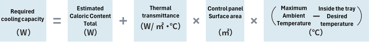
Basics of calculating required cooling capacity
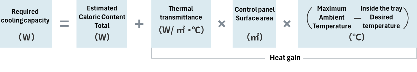
*Heat transfer coefficient: This varies depending on the material and thickness of panel, but for a typical panel, the guideline is 5 to 6 W/m²・℃, with 5 W/m²・℃ for a 2 mm thick steel plate being used as the reference value (standard).
※ panel Surface area: In the case of freestanding panels, it is the surface area that is effective for heat dissipation of panel, excluding the bottom area and the back area of the wall. (Effective surface area)
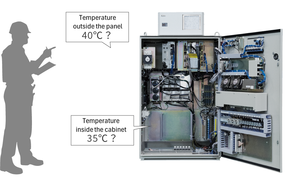
* Maximum ambient temperature: The highest temperature expected in environment where panel is installed, such as midsummer.
*Desired temperature in the board: The desired temperature is within the desired panel, and the recommended temperature is 35°C. Too low can cause condensation, and power consumption will also increase.
Key points for calculating required cooling capacity
Step 1. Obtain the estimated total calorific value of the equipment in the machine. (W)
Step 2. Check the external dimensions (H, W, and D) of the panel. (m)
Step 3. panel to see the number and area of contact with the floor and wall. (㎡)
Step 4.Find the effective surface area of panel from above. (㎡)
Step 5. Find the ambient temperature that is expected to be the highest, such as in midsummer.
From steps 6.1~5, ask for the required cooling capacity. (W)
*We recommend taking safety factor into account when calculating the required cooling capacity. (Recommended guideline: 1.2 to 2 times)
Quick explanation: The relationship between heat entering the panel and the ambient temperature
The heat intrusion on the right side of the equation is a positive value when the ambient temperature is high, as heat intrusion into the panel, and conversely, when the ambient temperature is low, as heat dissipation outside the panel, as a negative value.
A cooler location will result in less heat load.
However, please note that if the desired temperature inside the panel is increased, the lifespan effect will be reduced.
Basics of selecting the best cooler
cooler selection procedure
Step 1. Determine the required cooling capacity.
Step 2. Select either the side-mounted or ceiling-mounted type.


Step 3. From the product lineup, tentatively select a model with the required cooling capacity or more.
*We recommend taking into account safety factor when calculating the required cooling capacity. (Recommended guideline: 1.2 to 2 times)
Step 4. Check the cooling capacity characteristics graph of the selected cooler to see if it can provide more than the required cooling capacity capacity the actual temperature conditions.
cooling capacity listed in the catalog is capacity when the ambient temperature is 35°C and the inside temperature is 35°C, so cooling capacity will vary depending on the temperature conditions.
Required cooling capacity of cooler (W)≧Estimated total heat generation (W)
Quick explanation: cooling capacity characteristic graph
-cooling capacity of cooler (air conditioner) changes depending on the temperature conditions under which it is used (ambient temperature and temperature set inside the panel), so it is necessary to check cooling capacity according to the actual conditions of use.
• control panel cooling unit cooling capacity rating conditions are ambient temperature 35°C and in-machine set temperature 35°C.
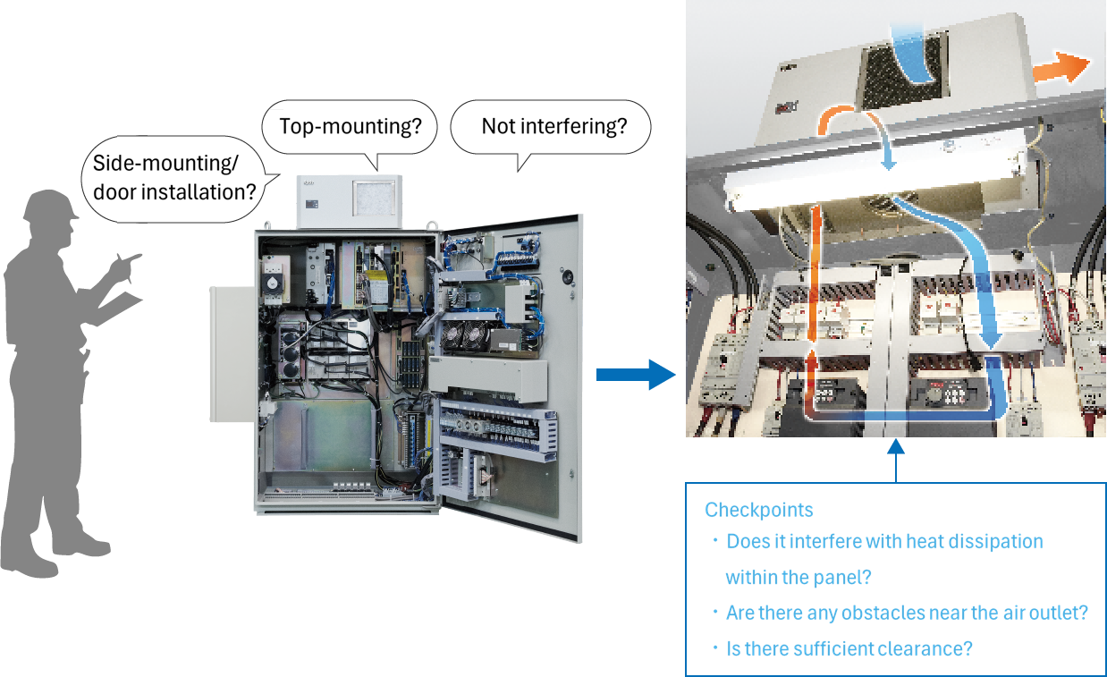
Quick explanation: What is the optimal installation location control panel cooling unit?
When deciding on the installation location of control panel cooling unit, please consider the following points:
Determine the optimum mounting location.
①Is there a circulation path for cool air inside the panel?
②Are there any obstructions on the ceiling, sides, or door of panel you want to install?
3) Is the exhaust heat from the self-cooling fans of the inverter and servo amplifier inside the panel not colliding with the cool air from cooler?
4) Are the external dimensions and panel cutouts of cooler you are considering suitable?
| Side-mounting | Ceiling Mounting | |
|---|---|---|
| merit | ・Easy installation -Easy filter and fan replacement ・Safe drainage |
・Doesn't take up much space ・Does not protrude into the aisle |
| Disadvantages | ・Protruding into the aisle ・Exhaust heat hits |
・Installation is at a high place ・Poor maintenance The monitor display is hard to see |
How to read cooling capacity characteristic chart
example)
- Internal heat capacity: 950W
- Maximum ambient temperature: 40°C
- Desired temperature inside the panel: 35℃
ENC-GR1000L-Pro (cooling capacity 1000W)
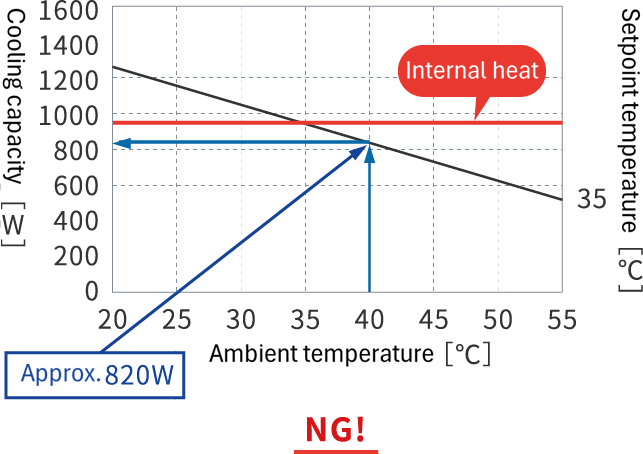
Under these conditions, cooling capacity is insufficient.
NC-GR1500L-Pro (cooling capacity 1500W)
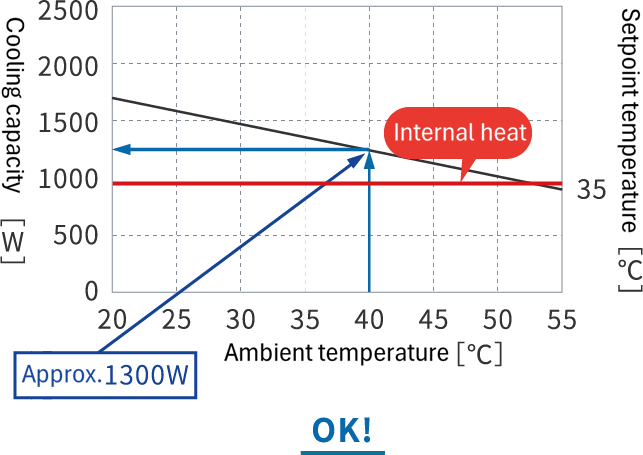
There is ample cooling capacity
Quick explanation: Why cooling capacity of cooler decreases as the ambient temperature increases
The reason why the cooling capacity characteristic diagram for control panel cooling unit slopes downward is due to cooler 's heat dissipation capacity.
Heat dissipation capacity is determined by the formula: heat dissipation area x heat transfer coefficient x (condenser temperature - ambient temperature). When the ambient temperature rises and the difference between the ambient temperature and the condenser temperature becomes smaller, the amount of heat that can be exchanged between refrigerant and the outside air in the condenser decreases, and cooling capacity of cooler also decreases.
When using in a location where high ambient temperatures are expected, cooler must be selected based on its actual cooling capacity.