

How to Choose
How to Choose
How to select oil chiller model
Selection flow
ACheck cooling capacity
① Determine the method for setting target values
oil chiller 's target value (SV) can be set using either an absolute value method where any value is input, or an input method from external temperature sensor.
SV value = absolute value (set to 35°C in the diagram below)
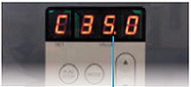
Set between 5℃ and 50℃
SV value = Aircraft temperature synchronization (external temperature input)
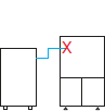
Oil Chillers
The set temperature changes in real time in sync with the temperature measured by X. The temperature can be adjusted within a measured temperature range of -9.9 to +9.9°C.
SV value = room temperature synchronization (external temperature input)
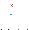
Oil Chillers
The set temperature changes in real time in sync with the temperature measured by X. The temperature can be adjusted within a measured temperature range of -9.9 to +9.9°C.
② Check the maximum Use Area Temperature
cooling capacity of an Air-cooling type oil chiller changes depending on the ambient temperature.
cooling capacity decreases as the ambient temperature increases, so please check the maximum Use Area Temperature.
③ Determine the minimum target temperature
Determine the target oil temperature. If you are using external temperature sensor, check the expected minimum temperature.
④Check cooling capacity of oil chiller
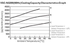
cooling capacity of oil chiller varies depending on Use Area Temperature, target oil temperature, and power supply frequency.
The graph showing this change characteristic is called the cooling capacity characteristic graph and is listed in specification section.
Example) cooling capacity of the VSC-N3200 (60Hz) under the following conditions is approximately 1700W, as shown in the graph on the right: ① Target value setting: (A) Absolute value control, ② Maximum ambient temperature: 30°C, ③ Minimum target temperature: 20°C or higher.
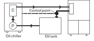
B Determine the control points
The control point (PV) of oil chiller can be selected from oil chiller outlet oil temperature or the oil temperature at any position (external temperature input).
PV value = outlet temperature
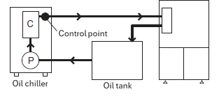
PV value = External temperature input (oil outlet piping on the device side)
C Check whether oil can be used
①Check whether the oil you are using meets specification of oil chiller
For oil chiller, use oil that meets all of the following conditions.
- ①Lubricating oil or hydraulic oil (mineral oil)
- ② Class 4 hazardous materials as defined by the Fire Service Act, including Class 3 and Class 4 petroleum products
- 3) Equivalent to discoloration number 1 in the petroleum product copper plate corrosion test method (JIS K 2513)
- ④Kinematic viscosity: 1.4 to 200 (ISO VG2 to 68) mm²/s
*Even if the oil meets all of the above conditions, deterioration may affect the product. We recommend regular oil maintenance.
The viscosity of oil changes depending on the temperature. Use the graph below to check whether the oil you are using meets the above specification.
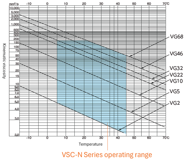
The graph above shows the characteristics of typical oils. There may be slight differences depending on the manufacturer and type of oil, so please check with the manufacturer of the oil you are using for details.
② Corrects cooling capacity
The cooling capacity characteristic graph of oil chiller shows the characteristics when ISO VG5 oil is used.
If you are using ISO VG5, use cooling capacity calculated in "B" as is.
When using ISO VG32, the viscosity of the oil is higher than that of ISO VG5, resulting in lower cooling efficiency.
Therefore, when using ISO VG32, cooling capacity will be approximately 90% of the value calculated in "B".
Example) ① Oil: When using ISO VG32, the corrected cooling capacity calculated with "B" is approximately 1728W using the following formula.
1920×0.9=1728 [W]
Please check whether cooling capacity calculated from A to C above exceeds the heat load of the equipment you are using.
* cooling capacity and heat load will vary depending on ambient environment, the condition of the oil used, and the operating conditions of the equipment. When deciding on a model, we recommend that you conduct a test to confirm in advance whether cooling capacity of oil chiller exceeds the heat load.
People who viewed this page also checked out these documents:

Please contact Apiste for oil cooling, which is essential for manufacturing.
Apiste 's oil chiller are HFC alternative and require zero CFC inspections work.
Same-day shipping is also possible. *Excluding some option items.
- I want to know how much capacity is required
- I want to know the compatibility with the model I am currently using.
- I want to know how much it will cost and when it will be delivered.

Contact by email