

Technical Information
液冷式熱交換器(液体―液体)
This explains the structure and features of liquid-cooled heat exchangers (liquid-liquid).
Roles and applications of liquid-cooled heat exchangers
A heat exchanger is a device that transfers thermal energy from a high-temperature fluid to a low-temperature fluid. It is used for heating and cooling by efficiently exchanging thermal energy using fluids such as liquids and gases. It is used in a wide range of applications, including industrial production processes and building air conditioning.
・Oil cooler for hydraulic press
・Mold cooling water cooler for injection molding machines
・Roller cooling water cooler
・Refrigerators, steam/hot water boilers, etc.
・Temperature control of hot springs and pools
・For air conditioning in buildings
Types of liquid-cooled heat exchangers
A liquid-cooled heat exchanger is a heat exchanger designed to efficiently exchange heat between two fluids without mixing them. There are many types of liquid-to-liquid heat exchangers, and they come in a variety of shapes, but here we will introduce the following five types of liquid-cooled heat exchangers that have a proven track record of use.
- Brazed plate heat exchanger (Apiste water-cooled chiller PCU-SL/PCU-R series)
- Gasketed Plate Heat Exchanger
- Shell and tube heat exchanger
- Throw-in type heat exchanger
- jacket tank
※液冷に使用される冷却水に関しては「冷却水の種類と特徴」をご覧ください
①Brazed plate heat exchanger
・Mechanism and structure
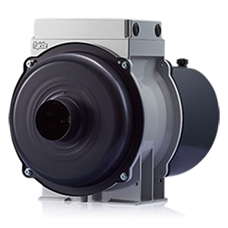
As shown in Figure 1 below, it has a structure in which electric heating plates are stacked, and the edges are sealed by brazing. From the standpoint of cost and workability, copper is often used for the brazing material. When clean specification are required in industries such as food, pharmaceuticals, and semiconductors, nickel brazing or stainless steel brazing can also be selected.
The structure allows high-temperature and low-temperature liquids to flow alternately through the gaps between the plates, enabling efficient heat exchange, and making the device compact for the amount of heat exchanged. As shown in Figure 2 below, creating a "counterflow" where high-temperature and low-temperature liquids circulate in opposite directions is advantageous for heat exchange efficiency.

Figure 1. Brazed plate heat appearance

Figure 2. Brazed plate heat exchanger structure
·Features
○It is small compared to the amount of heat exchanged.
○Comparably low cost.
○Since the flow path is narrow and decomposition is not possible, there is a possibility of clogging with solid matter.
②Gasket plate type heat exchanger
・Mechanism and structure
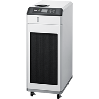
Like the brazed type, the plates are stacked and two types of fluid flow alternately, but in this case the plates are separated by a rubber gasket. By removing the fastening bolts that fasten the fixed plates on both ends, it is possible to perform maintenance on the plates and gaskets, and to increase cooling capacity by adding more plates. However, the size of the heat exchanger is slightly larger than that of the brazed type, so maintenance space must be taken into consideration when installing it.

Figure 3. appearance a gasketed plate heat exchanger
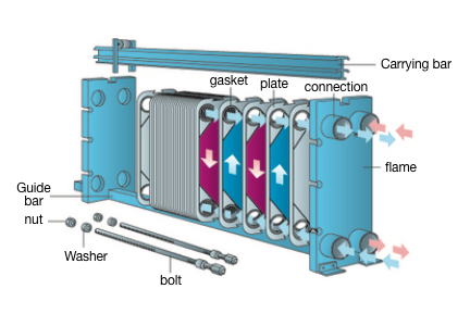
Figure 4. Gasket plate heat exchanger structure
·Features
○Although it is slightly larger than the brazing type, it is relatively small considering the amount of heat exchanged.
○The plate can be disassembled for maintenance.
Gasket materials can be changed according to specification.
③Shell and tube heat exchanger
・Mechanism and structure
A shell-and-tube heat exchanger is a heat exchanger that has tubes (heat transfer tubes) housed in a shell (body), as shown in Figures 5 and 6 below.
To obtain the same heat transfer area, the size is larger than that of a plate heat exchanger. However, because the shell (body) has a wide flow path and the tubes (heat transfer tubes) are branched into multiple parts, it can be designed to reduce fluid pressure loss and can also handle high-viscosity fluids. For this reason, it is also used in hydraulic equipment that handles high-viscosity oils, and in chemical plants.
It can be used for all applications, from low to high temperatures, low to high pressures, heating, cooling, evaporation, and condensation.
The structure is simple and can be disassembled (depending on the model), making maintenance easy.

Figure 5. Shell and tube heat appearance
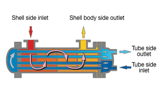
Figure 6. Shell and tube heat exchanger structure
·Features
○The size is larger than the plate type.
○It can be designed to minimize fluid pressure loss and can also handle high viscosity fluids.
It can be disassembled for maintenance.
High pressure resistance can be designed.
④Throw-in type heat exchanger
・Mechanism and structure
This is a cooling method in which a tubular or plate-shaped heat exchanger is immersed in a tank of the liquid to be cooled. This has the advantage of not requiring a circulation circuit for the liquid to be cooled, but in order to improve cooling efficiency, measures such as installing an agitator for the liquid to be cooled are required.

Figure 7. Tubular type (1)

Figure 8. Tubular type (2)

Figure 9. Plate type
·Features
Relatively easy to implement.
*The shape and heat transfer area can be designed to suit the tank size and shape.
○A mixer or other device is required to improve heat transfer efficiency.
○It is difficult to quantify the degree of mixing, so it is difficult to predict the amount of heat exchanged.
○If the cooling water temperature is low, condensation may occur and may get mixed into the liquid being cooled.
⑤ Jacket tank
・Mechanism and structure
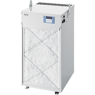
As shown in Figure 11, this tank has a double structure consisting of an inner tank and a jacket, and can cool, heat, or keep warm the contents placed in the inner tank. The temperature of the raw materials placed in the inner tank is controlled by circulating cold water or hot water in the jacket.
Generally made of stainless steel, they are easy to clean and are therefore widely used in food and pharmaceutical manufacturing processes. Compared to circulation-type heat exchangers, the heat transfer area is smaller and temperature unevenness is more likely to occur, so in such cases, an agitator is used to agitate the inner tank to improve heat transfer efficiency and make the temperature inside the tank uniform.

Figure 10. Jacket tank appearance
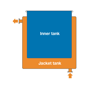
Figure 11. Jacket tank structure
·Features
Easy to clean, making it suitable for sanitary use.
○A mixer or other device is required to improve heat transfer efficiency.
○It is difficult to quantify the degree of mixing, so it is difficult to predict the amount of heat exchanged.
前の項目:空冷式熱交換器(液体―気体)
次の項目:チラーによる直接冷却
![Case study of the PCU-NE series of HFC alternative chillers [HFC alternative changes the workplace]](https://data.wovn.io/ImageValue/production/67edde949be8140853a05996/en/aabe45bb7302470507c7641e8f6439e3/bnr_case-pcu-ne.png)
People who viewed this page also checked out these documents:
Inquiry
For product inquiries, quote requests, etc.
Please feel free to contact us.