
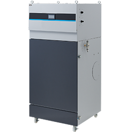
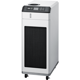
制御盤用クーラーの選び方

選定方法
機器別発熱量一覧
制御盤用クーラーの選び方
1.制御盤クーラー選定方法[屋内設置]
制御盤内を希望温度にするために必要な冷却能力は、下記の式で算出できます。
必要冷却能力[W]
= ① 制御盤内総発熱量[W] + ②熱通過率[W/m2・℃] × (③最高周囲温度[℃] - ④盤内希望温度[℃]) × ⑤制御盤有効表面積[m2]
①制御盤内総発熱量
盤内に収納されている機器の発熱量の合計。
※各機器の発熱量は ⇒機器別発熱量一覧表 を参照ください。
② 熱通過率
盤外から盤内へ侵入しようとする熱の通過率。
板金種類や板厚で変化しますが、板厚2mmの鋼鈑では約5[W/m2・℃]となります。
③ 最高周囲温度
設置される環境において最も高いと想定される温度。
④ 盤内希望温度
希望される盤内温度(推奨温度は35℃です)。
⑤ 制御盤有効表面積
対象制御盤の大気と接触する全ての面の表面積合計(自立盤の場合は底面を除いた表面積)。
2.制御盤クーラー選定方法[屋外設置]
屋外設置の場合には、1.制御盤クーラー選定方法[屋内設置]で算出した屋内設置の制御盤クーラーの選定結果に太陽光からのエネルギー量を加えて選定します。
必要冷却能力[W]
= 総日射侵入熱量 + 屋内盤としたときの必要冷却能力(1.制御盤クーラー選定方法[屋内設置]項目参照のこと)
総日射侵入熱量の求め方
1)日射による侵入熱量を計算します。
日射量は設置場所、日付、時間、方位によって異なります。
★各面の日射量サンプルデータ(東京地区、7/22快晴) 単位W/m²
| 天面 | 北面 | 東面 | 南面 | 西面 | |
|---|---|---|---|---|---|
| 11時 | 1026.7 | 302.8 | 302.8 | 305.1 | 77.3 |
| 12時 | 1064.0 | 78.3 | 78.3 | 325.9 | 78.3 |
| 13時 | 1043.0 | 78.8 | 78.8 | 310.1 | 307.7 |
| 14時 | 980.2 | 79.1 | 79.1 | 261.7 | 523.3 |
| 15時 | 872.1 | 80.7 | 80.7 | 179.8 | 715.3 |
このため各面ごとに計算して、その総和が必要な日射侵入熱量となります。各面の日射熱量は下記の計算式によって求められます。
各面の日射量[W/m²] ×
語句説明
- 「熱通過率(W/m²・℃)」・・・周囲温度(筐体表面上昇温度)と希望温度の温度差がある時、熱伝導により侵入(又は放熱)する熱量の対面積比率 制御盤の板厚、材質により変動しますが、盤用熱関連機器工業会で5~6W/m²・℃と規定されています。
- 「筐体外側の熱伝達率(W/m²・℃)」・・・無風時のときで約10W/m²・℃、風速1~2m/sのときで約15W/m²・℃と考えられます。風速が高いほど熱伝達率は大きくなります。
- 「筐体表面上昇温度(相当外気温度上昇)」・・・日射による気温の等価温度上昇のことです。
以上のことから、設置される地域、盤表面の色・状態、盤外壁の状態(厚み・2重構造・日除け板の設置etc.)、盤外を対流する風の状態などによって変動することがわかります。
例として下記条件の制御盤で計算してみます。
◎高さ2000mm、幅1000mm、奥行500mm◎扉面南向き◎東京地区、7月22日、快晴、14時、無風状態◎板厚2mm、塗装色:ライトベージュ、壁面は1重構造
| 面の位置 | 日射量 (W/m²) |
太陽吸収率 | 筐体外面 熱伝達率 (W/m²・℃) |
相当外気 温度上昇 (℃) |
熱通過率 (W/m²・℃) |
面の面積(m²) | 日射熱量(W) |
|---|---|---|---|---|---|---|---|
| 天面 | 980.2 | 0.5 | 10 | 49.01 | 5 | 0.5 | 122.5 |
| 北面 | 79.1 | 0.5 | 10 | 3.955 | 5 | 2 | 39.6 |
| 東面 | 79.1 | 0.5 | 10 | 3.955 | 5 | 1 | 19.8 |
| 南面 | 261.7 | 0.5 | 10 | 13.085 | 5 | 2 | 130.9 |
| 西面 | 523.3 | 0.5 | 10 | 26.165 | 5 | 1 | 130.8 |
| 総日射侵入熱量 | 443.6 | ||||||
注意! 使用年月とともに盤の表面がくすんで来たりすると吸収率が変化しますので、安全率を見た選定が必要です。
3)上記必要冷却能力を各制御盤クーラーの能力特性グラフに当てはめて選定してください。
《選定についての注意》
- インバーターやサーボアンプなどは、その使用方法・モータートルクなどによって発熱量が大きく変動しますのでご注意ください。
- 定格出力50kw以上のインバーターについては、メーカーによって発熱量が大きく異なりますので、メーカーにご確認ください。
- 機種を選定する際には、必要定格能力及び必要冷却能力を上回る機種を選定してください。
- 上記の計算式によって算出された能力は目安であり、絶対値ではありませんのでご注意ください。
- 制御盤の密閉性・発熱体との位置・盤内の対流によっては期待される冷却能力が得られない場合がありますので、十分にご注意ください。
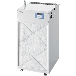
- フィルターの汚れやファンモーターの劣化等によって、冷却能力の低下に繋がる場合がありますので定期的なメンテナンスをしてください。
機器別発熱量一覧
1.電源・変圧機器類
| 盤内収納機器 | 発熱量(目安値) | 備考 | ||||||||||||
|---|---|---|---|---|---|---|---|---|---|---|---|---|---|---|
| 小型トランス | 定格容量
|
|
||||||||||||
| 大型トランス (単相) |
定格容量
|
|||||||||||||
| 大型トランス (三相) |
定格容量
|
|||||||||||||
| 電圧調整器 | 定格容量の10%程度 | |||||||||||||
| 大型抵抗器 | 定格容量の1/3程度 | |||||||||||||
| 定電圧電源 | 定格容量
|
|||||||||||||
| 無停電電源装置 (UPS) |
出力容量
|
|
||||||||||||
| 直流安定化電源 (スイッチングレギュレーター) |
定格容量の20~30%程度 |
|
||||||||||||
| 低圧コンデンサー | 定格容量の0.2~0.3%程度 |
|
2.増幅器類
| 盤内収納機器 | 発熱量(目安値) | 備考 | ||||||||||||||||||||||||||||||||||||||
|---|---|---|---|---|---|---|---|---|---|---|---|---|---|---|---|---|---|---|---|---|---|---|---|---|---|---|---|---|---|---|---|---|---|---|---|---|---|---|---|---|
| ACサーボアンプ | 定格容量
|
|
||||||||||||||||||||||||||||||||||||||
| インバーター | 定格出力
|
|
||||||||||||||||||||||||||||||||||||||
| ACリアクトル (200V系) |
定格容量
|
|
||||||||||||||||||||||||||||||||||||||
| ACリアクトル (400V系) |
定格容量
|
|
||||||||||||||||||||||||||||||||||||||
| DCリアクトル (200/400V系) |
定格容量
|
|
||||||||||||||||||||||||||||||||||||||
| 制動抵抗・制御ユニット (200/400V系) |
定格容量
|
|
||||||||||||||||||||||||||||||||||||||
| サイリスター (単相) |
定格電流
|
|
||||||||||||||||||||||||||||||||||||||
| サイリスター (三相) |
定格電流
|
|
3.配線用機器類
| 盤内収納機器 | 発熱量(目安値) | 備考 | ||||||||||||||||
|---|---|---|---|---|---|---|---|---|---|---|---|---|---|---|---|---|---|---|
| 配線用遮断器 (MCCB) |
定格容量
|
|
||||||||||||||||
| 漏電遮断器(ELCB) | 定格容量 ~225A MCCB+ 5W程度 ~400A MCCB+30W程度(漏電電子回路部等) |
|
||||||||||||||||
| 電磁接触器 | 定格容量
|
|
||||||||||||||||
| 熱動形過負荷継電器 (サーマル) |
定格電流
|
|
||||||||||||||||
| 電磁継電器 | 一台当たり5W程度 |
|
4.制御用機器類
| 盤内収納機器 | 発熱量(目安値) | 備考 | ||||||
|---|---|---|---|---|---|---|---|---|
| 小型リレー |
|
|||||||
| ソリッドステートリレー (SSR) |
負荷電流値×1.8W程度 | |||||||
| 温度調節計 | 消費電流を発熱量とみなす。 | |||||||
| PLC | 小型PLC AC電源タイプ
標準PLC 電源ユニットの消費電力程度 |
|||||||
| パソコン | 電源ユニットの消費電力程度 | |||||||
| 液晶モニター | 一台当たり 20W程度 | |||||||
| タッチパネル | 一台当たり 100W程度 |
5.その他
| 盤内収納機器 | 発熱量(目安値) | 備考 | ||||||||||
|---|---|---|---|---|---|---|---|---|---|---|---|---|
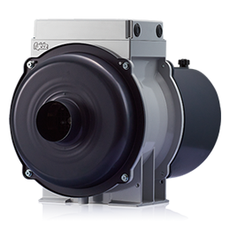
| ファンモーター |
|
|
注意! 上記機器別発熱量資料は盤用熱関連機器工業会発行の資料をもとに、当社独自に調査した資料を追加したものです。
各機器の発熱量は目安値になりますので正確な発熱量を求めたい場合は、各機器メーカーへお問い合わせください。
このページをご覧になった方は、こちらの資料もチェックしています
お問い合わせ
商品に関するご質問や、お見積のご依頼など
お気軽にお問い合わせください。