


How to Choose


When selecting chillers, it is crucial to choose a model that is suitable for the equipment and processes being cooled. Incorrect selection can lead to equipment problems and quality defects, such as failing to cool to the required temperature, insufficient flow rate, or inability to accommodate piping conditions.
There are two main methods for selecting chillers.
- When the equipment specification are determined
- If the equipment specification have not been determined
I will explain each case.
When the equipment specification are determined
If the required cooling conditions are clearly defined by the equipment manufacturer or in the equipment specification, we select chillers that meets those specification.
The main items to check are as follows:
- Set temperature
- Cooling capacity
- flow rate
- Lift
- Installation environment (indoor/outdoor)
- Cooling method (air cooling/water cooling)
for example,
- circulating water temperature: 25℃
- Required flow rate: 30L/min
- Required lifting height: 15m
- cooling capacity: 3kW
If the conditions are clearly defined, we will select a model that meets those specification.
Apiste chillers Lineup


If the equipment specification have not been determined
During the conceptual stage of equipment design or when setting up a new production line, the necessary specification may not yet be determined.
In this case, we first determine the configuration of the cooling circuit, and then organize the necessary specification.
① Decide whether to use an open circuit or a sealed circuit.
The first thing to check is the connection method to the object to be cooled.
In the case of an open circuit
An open circuit is a circuit in which the tank or vessel being cooled is open to the atmosphere.
for example,
- Plating tank
- Washing tank
- Chemical solution tank
- Large tank
These are some examples.
For open-circuit circuits, choose one of the following methods:
Use chillers without a water tank.
This system circulates the coolant directly.
While the configuration is simple and heat exchange losses are low, it may not be applicable depending on the type of circulating fluid and the equipment's conditions.
Use chillers and heat exchanger in the water tank.
This is an indirect cooling system that separates chillers side from the equipment side using a heat exchanger.
The liquid on the equipment side,
- chemical solution
- cutting oil
- Cleaning solution
It is often used in situations such as these.
A key feature is that the equipment fluid does not flow into chillers, making it easier to protection chillers.
In the case of a sealed circuit
A closed circuit is a circulation circuit in which the cooling water does not come into contact with the outside air.
for example,
- laser processing machine
- Semiconductor manufacturing equipment
- analytical equipment
- Molding / Forming machine
These are some examples.
For closed circuits, chillers with a water tank are generally selected.
Because temperature fluctuations can be absorbed through the water tank, stable temperature control can be achieved.
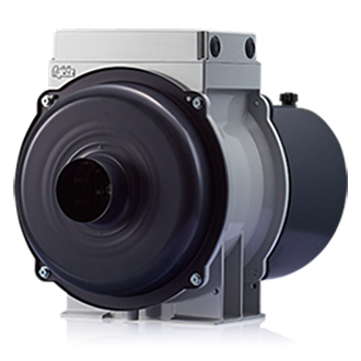
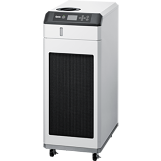
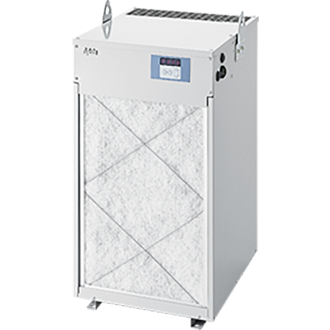
Apiste offers both models with and without aquariums in its lineup.
(chillers without a water tank)
(Aquarium with chillers)
② Confirm the required specification.
Once the circuit configuration is determined, we will confirm the required capacity.
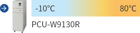
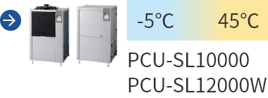
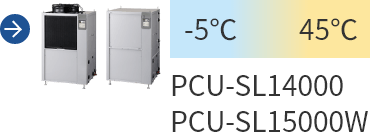
Set the temperature
First, determine the temperature required for the object to be cooled.
for example,
- Spindle cooling: 25℃
- Laser oscillator cooling: 22°C
- Cooling of Inspection equipment: 20℃
Each piece of equipment has its own appropriate temperature requirements.
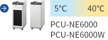
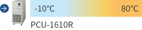
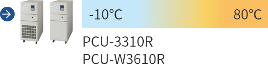
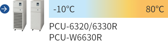
When selecting chillers, it is necessary to choose a model that can stably maintain the temperature.
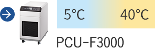
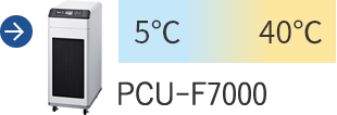
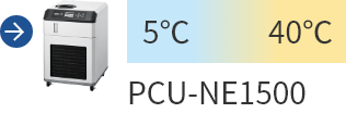
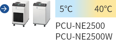
Apiste offers a lineup of chillers that can be used in a wide range of temperature conditions, so you can choose the right chillers to suit your diverse needs.
Determining cooling capacity
The required cooling capacity is determined based on the amount of heat generated by the equipment.
Insufficient cooling capacity can lead to problems such as the system not cooling down to the set temperature or the temperature remaining unstable.
The required cooling capacity is determined by heat calculations.
Please refer to the heat calculation method for details.
Furthermore, it is necessary to verify whether the selected chillers can provide sufficient cooling capacity under actual operating conditions in relation to the calculated heat output.
For more details, please refer to the instructions on how to check chillers capacity.
Determining pump capacity (flow rate and head)
chillers is equipped with a pump to circulate the cooling water.
We will check the required flow rate and head on the equipment side and select a model that meets those requirements.
The lifting height varies depending on factors such as pipe length, fittings, and elevation difference.
Please refer to the method for calculating head height for details.
③ Decide on the installation location (indoors or outdoors)
Next, we'll decide where to install chillers.
Indoor installation
For indoor installation,
- The piping distance can be shortened.
- Easy to use
- Easy to maintain
This is one of the advantages.
On the other hand, with Air-cooling type, the exhaust heat is released into the room.
Outdoor installation
Outdoor installation is,
- Using indoor space
- Less susceptible to the effects of heat dissipation
This is one of the advantages.
however,
- Rain protection measures
- Freezing prevention measures
- Pipe insulation
These will be necessary.
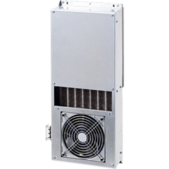
< Apiste 's chillers that can be installed outdoors>
Highly durable, energy-saving chiller
This chiller combines high energy-saving performance of up to 50% with durability that can withstand harsh field environment and outdoor use. It also has high-temperature precision and is suitable for a variety of applications.
④ Decide whether to use Air-cooling type or water-cooled system.
Finally, we select the cooling method.
Air-cooling type chiller
This method cools by exchanging heat with air.
merit
- No cooling water equipment is required.
- Easy to implement
- Relatively easy to maintain
Disadvantages
- Susceptible to ambient temperature changes
- Heat is generated.
Water-cooled chiller
This method cools by exchanging heat with cooling water.
merit
- High efficiency
- Less affected by ambient temperature
- Less heat is released into the room.
Disadvantages
- Cooling water equipment is required.
- Plumbing work is required.
Calculation methods required for chillers selection
When selecting chillers 's capacity,
(1) Heat load < (2) chillers cooling capacity
The selection will be made accordingly. The amount of heat load and chillers cooling capacity will be calculated using the following formula (calculation example and reference materials are available).
(1) Calorific value calculation method
Calorie calculation formula
Q [kW] =- Q: Load capacity [kW]
- ①Vs: Volume of object [m3]
- ②Cs: Specific heat of the object [kJ/kg・℃]
- ③γs: Density of the object [kg/m³]
- ④ΔT: Temperature difference of the object [℃]
- ⑤ t: Cooling time of the object [sec]
Calculation example (1)
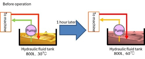
When the temperature of 800 L of hydraulic oil in a tank rises from 30°C to 60°C in 1 hour
From the physical properties table below, ②1.95, ③870, and ④60 - 30 = 30
Convert the units: ① 800 L = 0.8m3, ⑤ 1h = 3600sec
Substituting the above values into the formula,
(0.8 x 1.95 x 870 x 30 / 3600) x 1.2(safety factor) = 13.6 kW
Calculation example (2)
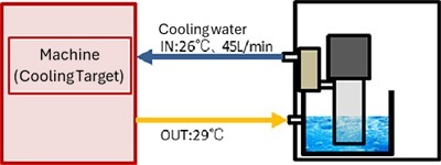
When the cooling water flowing into the equipment is IN: 26°C, OUT: 29°C, and the flow rate is 45 L/min
From the physical properties table below, ②4.18, ③998 ④29 - 26 = 3
If we break down the flow rate into a numerator and denominator and convert it into units based on the unit conversion table below, we get 36 L/min = 36 L / 1 min = 0.036 m3 / 60 sec. Therefore, ① 0.036, ⑤ 60
Substituting the above values into the formula,
(0.045 x 4.18 x 998 x 3 / 60) x 1.2(safety factor) = 11.3kW
*When the circulating solution is water, the temperature difference [ΔT] and flow rate [A] are calculated using the physical properties as coefficients.
It can also be calculated using the following formula:
Q[kW] = 0.07 × A[L/min] × ΔT[℃]
Calculation example (3)
After heat treatment, a 3 weight steel workpiece needs to be cooled from 250 to 40°C in 3 minutes.
From the physical properties table below, ②0.46 and ④250 - 40 = 210
Convert the units and get ⑤3 min = 180 sec
For ① and ③, the units can be converted as volume [m3] x density [kg/m3] = weight [kg], so ① x ③ = 3,
Substituting the above values into the formula,
(3 x 0.46 x 210 / 180) x 1.2(safety factor) = 1.93 kW
Unit Conversion Table
| ①Volume Vs | 50 L | = 0.05 m3 |
|---|---|---|
| 100 L | = 0.1 m3 | |
| 1000 L | = 1 m3 | |
| ②Specific heat Cs | 1 cal/g・℃ | = 4.18 kJ/kg・℃ |
| 1 kcal/kg・℃ | = 4.18 kJ/kg・℃ | |
| 1000 J/kg・℃ | = 1 kJ/kg・℃ | |
| ③Density γs | 1 g/cm3 | = 1000 kg/m3 |
| ⑤Time t | 1 min | = 60 seconds |
| 1 H | = 3600 sec |
Physical property table
- All values are at 20°C.
- The values in the table are for reference only. We do not take any responsibility for the results of calculations using this table.
| Substance name | ②Specific heat (kJ/kg・K) | ③Density (kg/m3) | |
|---|---|---|---|
| liquid body |
water | 4.18 | 998 |
| Water-soluble cutting oil (90% water) | 3.90~4.05 | 940~960 | |
| lubricating oil | 1.80~1.95 | 850~870 | |
| Spindle oil | |||
| hydraulic oil | |||
| gold genus |
Iron (steel) | 0.46 | 7870 |
| Aluminum | 0.91 | 2700 | |
| Copper | 0.39 | 8900 | |
| brass | 0.38 | 8500 | |
| Zinc | 0.39 | 7150 | |
| Non gold genus |
ceramic | 0.80 | 3600~3950 |
| Glass | 0.80~0.84 | 2600~2700 | |
| Bakelite | 1.59 | 1270 | |
| tree fat |
ABS (styrene butadiene, etc.) | 1.35~1.65 | 1000~1150 |
| EP (epoxy resin) | 1.10 | 1850 | |
| PC (Polycarbonate) | 1.25 | 1200 | |
| PE (polyethylene) | 2.30 | 910~960 | |
| PET | 1.25 | 1450~1670 | |
| PMMA (acrylic) | 1.48 | 1200 | |
| PP (polypropylene) | 1.95 | 900 | |
| PS (polystyrene) | 1.35 | 1030~1070 | |
| PVC (Polyvinyl Chloride) | 0.85~2.1 | 1160~1450 |
(2) How to check chiller capacity
Check the circulating water temperature (chiller set temperature), ambient temperature (if air-cooled), and cooling water temperature (if water-cooled), and calculate from the characteristics graph of the target model.
Example: Calculate cooling capacity of the PCU-3300R when circulating water temperature is 25°C and the ambient temperature is 20°C.
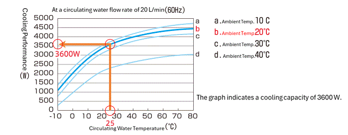
From the graph above, cooling capacity is calculated to be 3600W (selected at frequency 60Hz).
Lifting height calculation method
The pump power required to circulate cooling water can be expressed as "head."
The head varies depending on the condition of the piping connecting the chiller to the load (device), but the required head calculated from the pump capacity > piping is a condition. Below we will introduce how to calculate the head based on the piping conditions, etc.
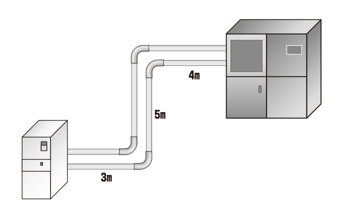
Step 1: Determine the pipe length.
Length of piping from chiller to device:
3+5+4=12m×2(round trip)=24m…①
Step 2: Convert the fitting resistance to straight pipe length and add it to the pipe length.
Obtain the equivalent straight pipe length of the fitting from the table.
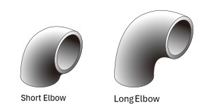
From the table...Threaded 90° short elbow 25A → 1.6m
1.6×4(places)=6.4m…②
①+②=24m+6.4m=30.4m…③
| name | Joint Shape | Pipe diameter (upper B) (lower mm) | ||||
|---|---|---|---|---|---|---|
| 1 | 1¼ | 1½ | 2 | 2½ | ||
| 25 | 32 | 40 | 50 | 65 | ||
| 90° Short Elbow |
Screw | 1.6 | 2.0 | 2.3 | 2.6 | 2.9 |
| Flange | 0.5 | 0.6 | 0.7 | 0.9 | 1.1 | |
| 90° Long Elbow | Screw | 0.8 | 1.0 | 1.0 | 1.1 | 1.1 |
| Flange | 0.5 | 0.6 | 0.7 | 0.8 | 0.9 | |
Since resistance varies depending on the shape of the joint, check the value converted into straight pipe length in the table above.
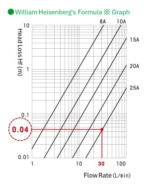
Step 3: Calculate the "head loss *Hf (m)" from the flow rate and pipe diameter and multiply it by the total pipe length from "Step 2".
When the flow rate is 30 L/min and the pipe diameter is 25 A, from the graph on the right, Hf = 0.04 Hf (m)…④
③×④=30.4×0.04=1.2(m)…⑤
*Head loss: Pressure due to pipe friction expressed per 1m of pipe length for each pipe diameter and flow rate.
※William Hazen Official
Hf=5.4775×10⁻³・C-1.85・D-4.87・Q1.85・L・α
(D: inner diameter of pipe, Q: flow rate, L: length of pipe, α: safety factor)
Step 4: Add the lift height from the chiller to the equipment to calculate the head.
Height from chiller to device: If 5m...⑥ ⑤+⑥=1.2(m)+5(m)=6.2(m)
The required lift is 6.2m…⑦
Step 5: Select a pump that satisfies the head calculated in step 4.
The chiller's head capacity shown in the graph is 35m (at 60Hz) when the flow rate is 30L/min.
Therefore, the head capacity of this chiller meets the required head (6.2 m).
35m > 6.2m
Example 1) When the circulating water flow rate is 30 m3/min, the head of the PCU-3310R is (when the required flow rate is greater than the rating flow rate).
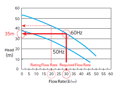
*From the graph above, the head is calculated to be 35m.
Summary of chillers Selection Process
When selecting chillers, first confirm whether the equipment's required specification have been determined.
If specification have not been decided,
- Decide whether to use an open circuit or a sealed circuit.
- Set the temperature
- Determining cooling capacity
- Determining pump capacity (flow rate and head)
- Decide on the installation location (indoors or outdoors).
- Decide whether to use Air-cooling type or water cooling.
By considering these factors in this order, you can efficiently select chillers that is suitable for your equipment. In particular, insufficient cooling capacity and pump capacity can cause problems, so it is important to select a model with sufficient margin.
Related Content



Contact Us
Please feel free to contact us with any questions about our products or to request a quotation.